My friend James and I created a guitar pedal used to create a soft clipping effect for an electric guitar. The circuit consists of an OPAMP, diodes, and filters to achieve the desired sound.
In my electronics class, the class was given the opportunity to do a bonus project where students had to get into small groups, create a circuit that used one or more of the topics we had learned in the class, then present that circuit to the class. My friend James and I decided to partner up to work on the project. He plays some guitar and proposed the idea of creating an electric guitar pedal. For those unaware, a guitar pedal takes the signal from an electric guitar and distorts it to create a unique sound.
After doing some research, we decided to create an overdrive pedal (also known as a soft clipping pedal). It gets this name from the “soft clipping” effect it puts on signals, which causes the peaks of the sound signal to be rounded off. We chose this kind of pedal for a few reasons. Firstly, the circuit contained unique applications of OPAMPS, diodes, and capacitor’s frequency response, which were all topics we covered in the class. On top of that, the application of these concepts was unique in the context of an overdrive pedal, making it extra appealing. The second reason was that every section of the overdrive pedal circuit was unique, which would help us retain attention while giving the presentation. Thirdly, overdrive pedals can vary a lot, and these variations were well documented, so we felt we could afford to experiment more with the sound of the pedal than the more complex and less documented pedals.
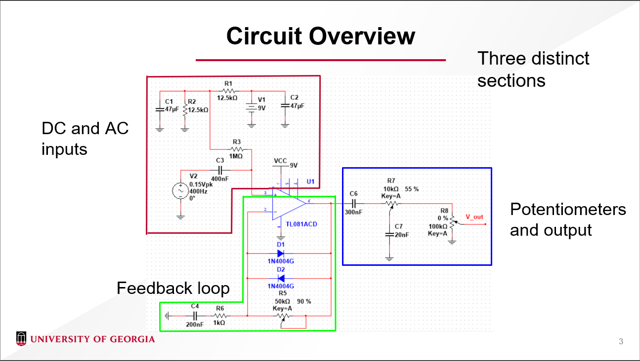
Now that we had decided what our project was, James and I began work on the circuit. After drawing inspiration from other circuits found online, along with experimenting with different ideas in simulation software NI Multisim, we had a final iteration of the overdrive pedal circuit. The circuit can be split into three different sections: Input, Feedback, and Output (see presentation “Circuit Overview/Analysis” slides). At the center of our circuit is an OPAMP supplied with a 9 V positive voltage supply, and the negative voltage supply grounded. We chose to do this (as opposed to making the positive supply 4.5 V and the negative supply -4.5 V) because the circuitry needed to take a 9 V battery and turn it into positive and negative 4.5 V was more complex than another solution we found to get the OPAMP distorting our signal. The solution found was to take our signal and give it a 4.5 V DC offset (seen in the input portion of the circuit). To do this, we have a voltage divider circuit (with some capacitors to filter out any AC noise) that delivers 4.5 V to the non-inverting input of the OPAMP. Connected to the non-inverting input is our electric guitar signal, with a coupling capacitor separating the signal and the input leg. This coupling capacitor superimposes the AC signal onto the 4.5 VDC, giving us our desired input.
The next major portion of the circuit is the feedback loop. The actual feedback loop itself consists of two diodes, each pointing in the opposite direction, and a 50 kOhm potentiometer, all in parallel connecting to the inverting input. Connected to the inverting input node, there is a 1 kOhm resistor in series with a de-coupling capacitor that leads to ground. This portion of the circuit is what gives us the soft clipping effect. Because we have negative feedback present, the OPAMP’s output will always be the value that makes the inverting input’s voltage equal to that of the non-inverting input’s voltage. The inverting inputs voltage is given by the voltage across the 1 kOhm resistor. Because of the de-coupling capacitor, no DC current can flow across the resistor, and the DC signal is not amplified. However, the de-coupling capacitor allows AC current to flow, meaning our AC signal is the only voltage amplified. When the current across the 1 kOhm resistor is low enough that the diodes in the feedback loop do not let current flow through them, the feedback loop behaves as a regular non-inverting amplification circuit. However, when the current needed across the 1 kOhm resistor is high enough, one of the diodes activates. Because of the exponential relationship between voltage across a diode and the current through the diode, the change in output voltage required to generate sufficient current across the 1 kOhm resistor decreases. This gives us the desired soft clipping effect (see slides 6 and 7 for a visual demonstration of this). Finally, the potentiometer can be adjusted to change the amount of soft clipping (as a smaller resistance means less clipping).
Now that we have our desired distorted signal, we can start on the output portion of the signal. This section connects to whatever sound system is used to record or play the guitar. First, we have a de-coupling capacitor to get the DC offset out of our signal. Then, our signal connects to a 10 kOhm potentiometer, with its wiper terminal connected to a 20 nF capacitor, and its third terminal connected to a final 100 kOhm potentiometer. This final potentiometer’s wiper terminal represents the output signal of the entire circuit, while the third terminal is connected to ground. The first potentiometer simply acts as a variable low pass filter. As the potentiometer is adjusted, the frequency response changes, varying the amount of high frequency signal through it. The final potentiometer is volume control. As the potentiometer is varied, the amplitude of the output changes.
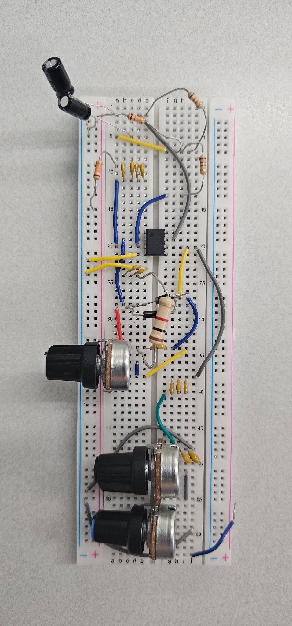
All that was left to do was construct the circuit and test it. We ordered all the parts we needed and constructed it on a breadboard. During testing, we found that the circuit worked as expected, but there were a few small issues with it. One was that there was some residual noise created at the output. This was not too bad, but if we were to iterate on the design, we would likely include some anti-noise measures. Another issue we found was that the low pass filter in the output portion of the circuit was not extremely significant. You can see this fact on slide 11 of the presentation. There was some difference between the output signals when the potentiometer on the filter was adjusted, but not as much as we would have hoped for. If we iterated on the design, we would likely include a different adjustable low pass filter to increase the effectiveness of the tone adjustment.
After testing, all that was left to do was create and give the presentation to the class. I’ve included the presentation as a downloadable file in the Links/Files section of this page if you would like to look at it. I’ve referenced it a few times here and it really helps visualize how the circuit distorts the sound. James and I really enjoyed working on this project and we felt it was a big success. Although the circuit did not turn out perfectly, we learned a lot about using OPAMPs, diodes, and coupling capacitors to amplify and distort signals. It was also a very fun practical example to work on. A lot of times in classes I take I am left wondering how what we are working on is used in real applications, and this was a good example of that. Finally, I was to give a big thanks to my friend James who helped me with this. He’s the one who initially came up with the idea and helped tremendously throughout the project.